| An amateur's question about the convenience of
recommending the construction of a low cost and low performance, small
"tailless" sailplane, motivated the statements made by Doctor Reimar Horten,
which are transcribed below, that will be of great interest for all the
motorless flight enthusiasts in our country.
As small sailplanes
for performance flights, I consider the motorless aircraft of a minimum
span of 12 meters, being the lower limit that assures satisfactory results
in soaring flight.
The convenience
of building this sailplane in the shape of a tailless aircraft, has to
be studied under the following points of view:
Can materials and handwork
be saved by building a tailless glider? Is it possible construction can
be done by a group of amateurs? Are its flight characteristics and
true performance satisfactory, and can they be compared with that of other
gliders of the conventional tailed type?
In the "tailless"
construction, there are two equivalent solutions, but issued by different
treatments of the same problem.
I.- The solution in the shape of a flying wing
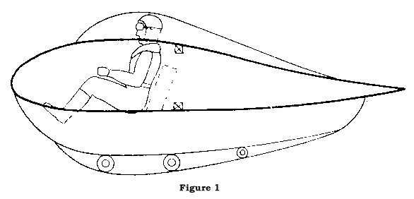
 Starting from the point of situating the pilot in a conventional position,
that is, seated, it brings as a consequence a very deep airfoil chord at
the wing root. Even, positioning a pilot's head in a "cabin-lid" that protrudes
out of the airfoil and using a keel for the skid in the bottom, we would
obtain an airfoil 40 to 50 centimeters [0.4 to 0.5 meters -Trans]
high, and so, a deepness of about 2.5 meters. (Figure 1, click on drawing).
With a wing area of
16 to 18 square meters and its corresponding aspect ratio not higher than
9, this would mean a glide ratio of 1:22 as maximum. Sinking speed
would be about 70 centimeters per second [2.3 feet per second
-Trans.], logically conditioned to wing loading.
This stating of the
problem was solved with the Horten Model I aircraft that took part successfully
in 1934 Rhön Soaring Flight Contest, and was a "calm winds sailplane"
prototype. The wing loading in this type was kept under 10 Kg/m2 and this
allowed very reduced flight speeds, that made it very convenient for using
the slow winds of the hills. As these sailplanes for calm winds were
ideal for making small diameter turns, they were very appropriate for rising
current flights of big height and duration. Also, they can be used
for making interesting long distance flights following the wind direction,
but when the target is to get high cruise speeds, as in the case of long
distance flights with known destination, or in flights were distance is
going to be worked against the wind, the low wing loading sailplanes will
not produce satisfactory results.
Comparing the described
sailplane with another built in the conventional way with a tail and same
span, we will notice that the lower drag of the flying wing will not compensate
the disadvantage in the speed polar curve caused by the smaller wing loading.
This means that in fast flight, the flying wing is only superior to a conventional
sailplane, when wing loadings are equal. Additional advantages can
be expected from the design with laminar airfoils, benefits that will be
noticeable in the flying wing due to the big airfoil chord.
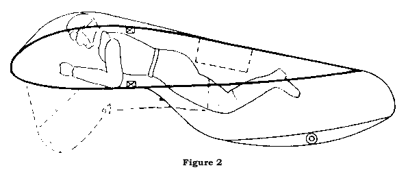
 The disadvantages that come from a low aspect ratio and consequent low
wing loading, will be avoided by building a sailplane with the pilot laying
on his belly (Figure 2).
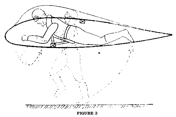
Another interesting
development possibility is for the flying wing with the pilot in a "hanging"
position, as in primitive gliders, where the pilot is horizontal with his
legs retracted inside the wing airfoil. In this way, not only the
construction cost will be reduced, but also maintenance and flight conditions
will be simplified, considering that the craft transport and its
launching can be made with only the use of the pilot's legs.
Fixing as a condition the existence of a hill from which it can be possible
the take off with a short pilot run, this flying wing model would allow
to achieve duration, height and distance performances without any personnel
assistance.
In the old "hang pilot"
gliders it was usual to maneuver by displacement of the pilot's center
of gravity. I don't recommend such a system and propose to build
them with the usual control system. Minimal sinking speed will be
about 50 and 55 centimeters per second [1.6 to 1.8 feet per second -Trans.]
and optimal gliding angle will be 1:22. Reduced wing loading will
allow the pilot to find and  target
rising currents very easily and they will be able to be used by turning
with a small bank, in the way of a dry leaf. All these factors will
permit getting remarkable records in soaring flight, so I must suppose
that this "laying pilot flying wing", will call the attention of people
interested in the subject, mainly if it can be used as a "rising
current finder" working in combination with high performance sailplanes
of big span. target
rising currents very easily and they will be able to be used by turning
with a small bank, in the way of a dry leaf. All these factors will
permit getting remarkable records in soaring flight, so I must suppose
that this "laying pilot flying wing", will call the attention of people
interested in the subject, mainly if it can be used as a "rising
current finder" working in combination with high performance sailplanes
of big span.
II- The solution in the shape of a tailless sailplane
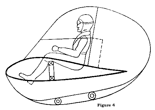
My idea about it is a
craft with big span swept wings and with an ovoid fuselage "piece" fitted
by its half height portion, on the wing, in which the pilot will be put
in a seated position. This design will allow  glide
a ratio of up to 1:26, within the 12 meter span, that will allow us to
compare it - even at high speeds - with the usual high performance sailplanes.
Based on the normal wing loading of 18 to 20 kg/m2, the minimum sinking
speed will be about 60 centimeters per second [2 feet per second
-Trans.] (Figure 4). glide
a ratio of up to 1:26, within the 12 meter span, that will allow us to
compare it - even at high speeds - with the usual high performance sailplanes.
Based on the normal wing loading of 18 to 20 kg/m2, the minimum sinking
speed will be about 60 centimeters per second [2 feet per second
-Trans.] (Figure 4).
Without using laminar
airfoils and the laying pilot position, I consider the sketched model as
the ideal solution for the "high performance small glider" constructive
problem.
It is understood
that a flying wing or a tailless small glider will not be disassembled
and, so, will always be transported as a sole piece. For this reason
construction will be notably cheaper and simpler, saving, by the way, superfluous
weight. For the same reason of weight and simplicity, high-lift
flaps are not added, they are unnecessary for the landing due to the already
reduced speed, and in rising current soaring they don't bring any advantages.
In other words: the increase in sinking speed with flaps, has more influence,
than the compensation produced by a smaller turn radius at the same bank,
motivated by the increase in lift coefficient, so, with the flaps a higher
ascension in rising currents cannot be achieved.
As a rudder, I
have been using to date with excellent results the wing tip brakes.
I consider that any modern sailplane requires brake devices against exaggerated
speeds and as a glide angle control during landing. In the tailless
aircraft, I moved this same device towards the wing tips and made them
take the role of a rudder as well. For the combined function of ailerons
and elevator, two surfaces of size and location as in conventional ailerons
are enough, which brings a notable advantage in weight.
If after considering
the described possibilities I compare both airplanes, one with a tail and
the other without a tail, with the condition that both have the same span
and wing loading, I notice that the tailless airplane will have less wing
surface and so, a bigger aspect ratio. From that I deduce that the
same tailless sailplane will have a smaller cost in materials and work,
with better flight performance.
Examining in detail
the three factors: materials cost, flight characteristics and construction
work, I notice the following differences between small gliders with and
without a tail:
On one side, all
tailless small gliders suffer a charge of 5% in the basic wing weight,
produced by the sweep of 20 degrees in the spar (I call basic wing weight
to be the weight that results from dividing wing weight by its surface).
On the other side,
weight reductions are produced by the following reasons:
a) Elimination of the fuselage section
fore of the wings, and so, a reduction in the craft length of between 1.20
and 1.50 meters.
b) Elimination of the fuselage part that
holds the empennage.
c) Elimination of the elevator, because
ailerons take its function, without weight charge.
d) Elimination of the rudder, because the
brake devices take its function, without weight charge.
e) Elimination of one control system, because
the aileron control works in combination, as an elevator control.
f) Elimination of mounting lugs, because
it is possible to transport the glider by highway, without disassembling,
due to its reduced length.
g) Smaller wing surface at an equal wing
loading to that of a conventional sailplane.
As far as flight characteristics
are concerned, I want to state first of all, the excellent behavior observed
in my sailplanes during the stall. The swept wings give the tailless
airplane a longitudinal damping that is superior in about twice as much
as the one of a conventional airplane; so, despite its smaller inertia
moments, all movements about the transverse axis happen with the same angular
speed. The gust sensitivity is the same in all sailplanes, in tailless
sailplanes as well as in tailed ones, because it depends, first, on the
wing loading, this is, weight.
Neither by aircraft
stability nor by the controls reaction, can a pilot say that he is flying
a tail or tailless airplane; so, mind tiredness happens in both alternatives
by the same amount.
Speaking about
the differences in work between the construction of one or another airplane,
I consider that the construction of a small tailless glider is not more
complicated than the same with a tail. The increase in work that
it takes to make swept wings as compared to straight wings, is smaller
than the one of making tapered ones as compared to the same straight ones.
About the wing twist, this must be calculated in excess, to compensate
for deficiencies that can appear during the construction by a group of
amateurs. The losses in aerodynamic shape that happen in this way
are the same in any case, but they will not be able to be avoided without
using special assembling and checking devices.
Summarizing all
before mentioned, I affirm that I consider as promissory the development
of a performance small-glider, be it built as a flying wing with a "laying
pilot" or as "tailless small-glider with a seated pilot".
........... ...12/7/01.......................................Back
to Index......................................Back
Home... ...12/7/01.......................................Back
to Index......................................Back
Home...
|
|
Veleritos "sin cola"
La
pregunta de un aficionado sobre la conveniencia de recomendar la construccion
de un pequeño velero "sin cola", de bajo costo y performances discretas,
motivo las declaraciones que transcribimos, del Doctor Reimar Horten, que
resultaran de indudable interes para todos los entusiastas del vuelo sin
motor en nuestro pais.
Como veleritos para vuelos de performance, considero al avion sin motor
de 12 metros de envergadura minima, por ser este el limite inferior que
asegura resultados satisfactorios en el vuelo a vela. La conveniencia
de construir este velero como avion sin cola, debe estudiarse desde los
siguientes puntos de vista:
Puede ahorrarse material y mano de obra construyendo un velerito sin cola?
Es factible la construccion del mismo por un grupo de aficionados? Son
satisfactorias sus caracteristicas de vuelo y las performances realizables
y pueden compararse las mismas con las de otros veleritos del tipo convencional
con cola?
Dentro de la forma de construccion "sin cola", se presentan dos soluciones
equivalentes, pero surgidas de planteos distintos del mismo problema.
I.- La solución en
forma de ala volante
 Partiendo de la base de situar al piloto en la posicion convencional, es
decir, sentado, trae como consecuencia una cuerda de perfil muy profunda
en la raiz del ala. Aun, ubicando la cabeza del piloto dentro de una tapa-cabina
que sobresalga del (... figura 1 ...) perfil y empleando una quilla para
el patin que resulte de la parte inferior, se obtendra un perfil de unos
40 a 50 centimetros de
altura y, por consiguiente,
una profundidad de unos 2.50 metros (Fig 1).
Con una superficie alar de 16 a 18 metros cuadrados, con su correspondiente
alargamiento no mayor de 9, significaria una relacion de planeo de 1:22
maximo. La velocidad de descenso estara en los 70 centimetros por segundo,
condicionada logicamente a la carga alar.
Este planteo del probelma fue resuelto con el modelo Horten I, aparato
que intervino exitosamente en el Concurso de Vuelo a Vela del Rhön
de 1934, y fue un prototipo "velero para vientos suaves".
La carga alar de este tipo se mantenia inferior a los 10 kg/m2 y permitia
velocidades de vuelo muy reducidas, que lo hacia muy conveniente para el
aprovechamiento de los vientos suaves de las colinas. Como estos veleros
para vientos suaves son ideales para realizar virajes de poco diametro,
resultan muy apropiados para vuelos a vela termicos de altura y duracion.
Tambien con ellos pueden realizarse vuelos de distancia interesantes a
favor del viento, pero cuando se trata de alcanzar altas velocidades de
crucero, tal como se necesita en los vuelos de distancia con destino anticipado,
o en los vuelos en que se desee ganar distancia en contra del viento, los
veleros de baja carga alar no daran resultados satisfactorios.
Comparando al velero descrito con otro construido en la forma convencional
con cola y de la misma envergadura, notaremos que la resistencia menor
del ala volante no llega a equiparar la desventaja producida en la curva
polar de la velocidad por la menor carga alar. Esto significa que en el
vuelo rapido, el ala volante es solo superior a un velero convencional,
cuando las cargas alares son
iguales. Pueden esperarse
ventajas adicionales con el diseño basado en perfiles laminares,
beneficios que seran notablemente sensibles en el ala volante debido a
la gran cuerda del perfil.
 Las desventajas provenientes del alargamiento bajo y de la carga alar reducida
consiguiente, podran evitarse construyendo al velero con el piloto en la
posicion acostada boca abajo (Fig 2).
Otra posibilidad de desarrollo interesante se presenta para el ala volante
con el piloto en posicion "suspendido", como en los primitivos planeadores,
es decir, el piloto se encuentra en posicion horizontal y con sus piernas
retraidas dentro del perfil alar. En esta forma, no solo se reducira
el costo de construccion, sino que tambien se simplificara el mantenimiento
y las condiciones de vuelo, ya que tanto el transporte del aparato como
su lanzamiento puede realizarse con el unico empleo de las piernas del
piloto. Fijando como condicion la existencia de una colina desde la cual
sea posible el decolaje con poca carrera del piloto, este modelo de ala
volante permitira realizar performances de duracion, de altura y de distancia
con viento a favor, sin la asistencia de personal alguno (Fig. 3).
En los antiguos planeadores del tipo "piloto suspendido" era normal maniobrar
por el desplazamiento del centro de gravedad del piloto. No recomiendo
tal sistema, y propongo construirlos con el sistema de mandos del tipo
corriente. La velocidad de descenso minima estara en los 50 a 55 centimetros
por segundo y el angulo de planeo optimo en 1:22. La carga alar reducida
permitira localizar y centrar las termicas con gran facilidad y se podra
aprovecharlas virando con poca inclinacion, a la manera de una hoja seca.
 Todos estos factores permitiran lograr marcas notables en vuelo a vela
, por lo que debo suponer que esta "ala volante de piloto acostado", llame
la atencion de los interesados, maxime si se considera que puede
ser utilizada a manera de "localizador de termicas" en combinacion con
alto-veleros de gran envergadura.
II- La solucion en forma
de velero sin cola
Mi idea al respecto es la de una maquina con alas en flecha de gran alargamiento
y con un "rudimento" ovoide de "fuselaje" tomado a media altura entre el
ala , en el cual el piloto se alojara en posicion sentada. Este diseño
permitira relaciones de planeo de hasta 1:26, dentro de la envergadura
de 12 metros,  lo
que permite compararlo -aun en altas velocidades- con los alto-veleros
usuales. Tomando como base una carga alar normal de 18 a 20 kg/m2, la velocidad
minima de descenso sera de unos 60 centimetros por segundo (Fig 4). lo
que permite compararlo -aun en altas velocidades- con los alto-veleros
usuales. Tomando como base una carga alar normal de 18 a 20 kg/m2, la velocidad
minima de descenso sera de unos 60 centimetros por segundo (Fig 4).
Prescindiento de los perfiles laminares y de la posicion acostada del piloto,
considero al modelo bosquejado como la solucion ideal del problema constructivo
"velerito de performance".
Se sobreentiende que un ala volante o un velerito sin cola no sera desmontable
y, por lo tanto, se transportara siempre como pieza unica. Esta razon abaratara
y simplificara notablemente la construccion, ahorrandose por otra parte
un peso superfluo. Por la misma razon de simplicidad y de peso, se prescinden
del agregado de aletas hipersustentadoras, innecesarias para el aterrizaje
por la velocidad de por si reducida, y que en el vuelo a vela termico no
reportan ventajas. En otras palabras: el aumento de la velocidad de descenso
con aletas, tiene mas influencia que la compensacion producida por un radio
de viraje menor a la misma inclinacion, motivado por el aumento del coeficiente
de sustentacion, de modo que con aletas no se logra un ascenso mayor en
las termicas.
Como timon de direccion he usado hasta la fecha con excelentes resultados
frenos en los extremos del ala. Considero que todo velero moderno requiere
aletas de freno contra velocidades exageradas y como control del angulo
de planeo en el aterrizaje. En el avion sin cola, trasplanto estas
aletas mas hacia los extremos del ala y las hago asumir a la vez la funcion
de timon de direccion. Para la funcion combinada de alerones y de
timon de profundidad, resultan suficientes dos aletas del tamaño
y ubicacion de los alerones convencionales, lo que reporta una ventaja
apreciable en el peso. Si luego de considerar las posibilides descritas
comparo a dos aviones, uno con cola y otro sin cola, con la condicion que
ambos tengan la misma envergadura y carga alar, observo que el avion sin
cola tendra menos superficie alar y por lo tanto un alargamiento mayor.
De ello deduzco que el mismo velero sin cola tendra un costo de materiales
y de mano de obra menor, con un rendimiento de vuelo superior.
Examinando al detalle los tres factores: costo de materiales, caracteristicas
de vuelo y mano de obra en la construccion, noto las siguientes diferencias
entre los veleritos con y sin cola:
Por un lado, todos los veleros sin cola sufren un recargo del 5% en el
peso basico alar, producido por la flecha de aproximadamente 20 grados
que forma el larguero (llamo peso basico alar al cociente que resulta de
dividir el peso de las alas por su superficie).
Por otro lado se producen reducciones de peso por las siguientes razones:
a) Supresion de la
seccion de fuselaje anterior a las alas y, por lo tanto, reduccion de la
longitud de la maquina de 1.2 a 1.50 metro.
b) Supresion de la
parte del fuselaje que sostiene el empenaje.
c) Supresion del timon
de profundidad, pues los alerones asumen su funcion, sin recargo de peso.
d) Supresion del timon
de direccion, pues las aletas de freno asumen su funcion, sin recargo en
el peso.
e) Supresion de un
sistema de comandos, pues el comando de alerones funciona en combinacion
como comando de profundidad.
f) Supresion de tomas
de montaje, pues resulta posible el transporte del velero por carretera,
sin desarmarlo, merced a su longitud reducida.
g) Menor superficie
de las alas a igual carga alar que el velero convencional con cola.
Con respecto a las caracteristicas de vuelo, quiero reafirmar ante todo
el excelente comportamiento observado en mis veleros durante el vuelo en
perdida de velocidad. Las alas en flecha dan al avion sin cola una amortiguacion
longitudinal superior en mas del doble a la del avion convencional; por
lo tanto, y a pesar de su momento de inercia menor, todos los movimientos
alrededor del eje transversal se producen con la misma velocidad angular.
La sensibilidad contra rachas es igual en todos los veleros sin cola que
en los con cola, ya que la misma depende, en primer lugar, de la carga
alar, vale decir, del peso.
Ni por la estabilidad de la maquina ni por la reaccion de los comandos,
un piloto puede asegurar que esta volando un avion con o sin cola; por
lo tanto, el cansancio mental se produce en ambas alternativas por igual.
Refiriendose a las diferencias de mano de obra que median entre la construccion
de uno u otro avion, considero que la construccion de un velerito sin cola
no es mas complicada que la del mismo con cola. El aumento de trabajo que
reporta hacer alas en flecha con relacion a las alas rectas, es menor al
que ocasionan las alas acodadas con respecto a las mismas rectas. En lo
que se refiere a alabeamiento alar, este debe calcularse en exceso, para
compensar deficiencias que pueden producirse durante la construccion por
un grupo de aficionados. Las perdidas de fineza aerodinamica que se producen
en esta forma son las mismas en todo caso, pero no podran evitarse sin
la aplicacion de dispositivos especiales de armado y control.
Resumiendo todo lo antedicho, afirmo que considero promisorio el desarrollo
del velerito de performance, ya sea construido como ala volante tipo "piloto
acostado" o como "velerito sin cola con piloto sentado".
............. ...12/7/01..................................Back
to Index......................................Back
Home... ...12/7/01..................................Back
to Index......................................Back
Home... |


