I have been trying to get the Australian Ultralight Federation to accept my concept of Waterhen, a 3-seater amphibian which you once featured in your newsletter which had a ply/foam backbone and, which I believe I could put in the air with a M.T.O.W. of 614 kgs. They have replied stating that only 2 persons can fly in an ultralight, the stall cant exceed 45 kts and much be single engined. What are the rules for ultralights in the U.S.? The only way they said I could go would be to become a G.A. pilot and register under Experimental with Civil Aviation, an extremely costly operation in Australia.
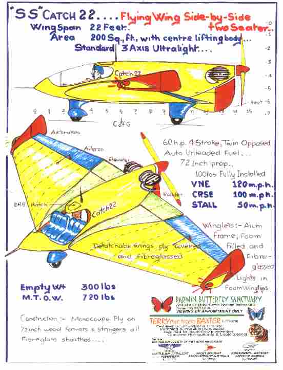
I have waited anxiously for a two-seater flying wing which is on many peoples minds. I am hoping to build my own under the Australian Ultralight Experimental banner and have started a concept called SS Catch 22, being 22 wing span and a two-seater side-by-side, hence the title. I have been informed that the WWI Albatross Scout Fighter was built by the women of Germany in 1916-17 and have since seen a video of the women stitching the ply to the frame of the fuselage of a drag free shape. Having built many fast sailing boats with ply, I believe with the 1/16 inch ply I could build a very light, strong ultralight 2-seater, side-by-side with the new 4-stroke 60 hp twin opposed air cooled engine for 300 lbs empty weight.
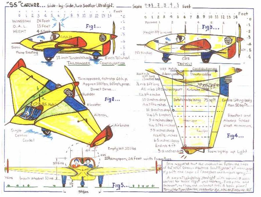
With a center fuselage and lifting body of 8 and two 7 detachable wings, it would fit on a 12 x 6 standard single wheel trailer and be legal on the roads in Australia. You are allowed 3 overhang and with the tri-landing gear it can be pushed up 3 planks for loading.
I have selected the 4-stroke engine as it has more guts in a climb and there is no mixing of the fuel, since it would use standard unleaded auto fuel. If I can cruise at 100 mph in a flying wing, which is all over the Drifters and Thrusters that I have flown and are the backbone of all Australian clubs, I would have the ultimate 2-seater ultralight as a general purpose utility and trainer. This monocoupe ply over a former framed shape fiberglassed must be economical as no molds have to be made, but would be time consuming in sanding before glassing, but all you would need is a flat floor to work off, even jigs are not required.
As you can see by the sketch below with the two root ribs of the fuselage identically made and, the 8 timber that takes the elevator at the rear and former No. 2 in position, the basic fuselage is formed and, formers 3, 4, 5 and 6 are added at 2 intervals. Level the frame on the floor and add full-length stringers in the center areas checking that the elevator timber is level.
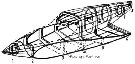
Place formers 7 and 8 between the stringers again at 2 intervals and brace to the floor. Place the No. 1 former in place pulling the stringers to a point and dock them off, tapering ends to join. The dart shape center lifting body is now shaped and must be checked that all is symetric to the center and the profile is correct.
Satisfied the framing is true and, as all the formers have pre notched equal distance add all the stringers allowing overlap for the proposed canopy top and body sides of the cockpit. Plane down all stringers to the formers shape (do not sandpaper) and nail on scrap ply to top and sides to hold shape in long thin lengths. Now turn the whole frame over on its back and add all the stringers to the bottom in the pre notched formers and the heavy keel piece from former No. 2 to the elevator timber. All stringers should be flush as it is level crossways. Only the stringers from former No. 2 to the point at the front need fitting and planning. When all the epoxy gap filling glue has dried in all the stringer joints, turn the fuselage upright again and level.
Check that the frame is symmetrical all over and braced level. Place ply full length on top of fuselage and mark area that requires little bending to put it in place keeping the line on the same stringer the full length. Remove and cut 3/8 inch inside line as stringer are ¾ inch and the joining sheet must butt against it. When the joining sheet is marked it must be cut 3/8 inch outside the line to butt up. As the ply is only 1/16 inch and epoxy glued, all those areas without tension can be fired on with a staple gun and stainless staples. Areas under tension are to be clamped until the epoxy is cured. When the main part of the top is covered, apply ply to both sides, doing the same to each side alternatively so no stress is applied to the fuselage. All difficult areas use steam heated ply using a spanish windless to held in place until dry. Then remove the windless and flush fit as the shape should be and retain with glue and staple into position.
When the sides and top are covered with ply, turn the fuselage upside down, clean out with compressed air and then spray with two coats of thin spraying epoxy that is compatible with that used for the gluing. Leave the bottom sheeting off until all internal work is completed. When dry turn fuselage right side up. Now the whole of the upper sides can be sanded and the profile of the cabin area finished off with wood inserts where required.
The canopy can be made professionally if money is available so it is in one piece. The other option is to form it in three separate pieces using small aluminum tubing for the frames and hinging the center section as a gull wing door closing with latches on the left hand side making it the pilots responsibility. The front and back piece can be epoxied to the fuselage. Use the new elastic type epoxy and use sloppy holes for any screws, bolts, etc. (Click to expand drawings.)
It is suggested that the demountable wings could be ply/foam ribs, all timber/foam spars, ply covered, fiberglassed with aluminum tubular extensions fitting into tubes located at formers at 2 feet, 6 feet and 10 feet positions, or alternatively could be all metal. All security for wings within the fuselage easily accessible. Front wheel is braced off formers at the 2 foot and 4 foot positions and the rear wheel is braced at the rear spar and trailing elevator support at the center lifting body.
Summary This concept is to produce a two seater ultralight as a common utility, cross-country, economically built and operated aircraft as a flying wing concept for the homebuilder from scratch plans which can survive Tiger Country of Australia outback and still be used to train people for the conventional 3-axis aircraft.
I am no aeronautical engineer, but have drawn what my gut instincts tell me might work. Having little knowledge of flying wings, but having had experience of the Thruster and Drifter 3-axis drag bags of cruising at 60 kts, feel that less drag flying wing would be the ultimate in a general utility all around aircraft. Remembering Pernauds flying wing concept of 1800s amphibian with the reflexed after wing shape that never was built, I am sure he had the right idea prior to the Wright Brothers.
I feel that the large elevator is an extension of the reflex of the center lifting body and would eliminate porposing making stable flight. The ailerons of the reflex wing can counter roll and, the under body rudder would control yaw in conjunction with the winglets that have been kept reasonably small for less drag, but big enough to mount airbrakes for short landings in Tiger Country. It would include a BRS to perch you on forests, mangroves and rocky areas fired through an overhead canopy which should shade occupants from the blazing hot sun of tropical Australia. If this concept is capable of cruising at 90 kts, about 100 mph, have short takeoff and landing ability, capable of being a trainer, then it must be the ultimate in ultralights. Please print the drawings in the newsletter for criticism and help with my address as I have no computer, e-mail, etc.
Terry (the Tiger) Baxter
79 Mueller Road; MALAK
DARWIN, Northern Territory
AUSTRALIA 0812